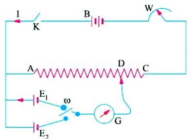
DC potentiometer is used for measuring and comparing the e.m.fs. of different cells and for calibrating and standardizing voltmeters, ammeters etc. In its simplest from, it consists of a German silver or manganin wire usually one meter long and stretched between two terminals as shown in Figure A.
Figure A
AdBlock-2
This wire is connected in series with a suitable rheostat and battery B which sends a steady current through the resistance wire AC. As the wire is of uniform cross-section throughout, the fall in potential across it is uniform and the drop between any two points is proportional to the distance between them. As seen, the battery voltage is spread over the rheostat and the resistance wire AC. As we go along AC, there is a progressive fall of potential. If ρ is the resistance/cm of this wire, L its length, then for a current of I amperes, the fall of potential over the whole length of the wire is ρ LI volts.
The two cells whose e.m.fs are to be compared are joined as shown in Figure A, always remembering that positive terminals of the cells and the battery must be joined together. The cells can be joined with the galvanometer in turn through a two-way key. The other end of the galvanometer is connected to a movable contact on AC. By this movable contact, a point like D is found when there is no current in and hence no deflection of G. Then, it means that the e.m.f. of the cell just balances the potential fall on AD due to the battery current passing through it. Suppose that the balance or null point for first cell of e.m.f. E1 occurs at a length L1 as measured from point A.
The E1 = ρ L1I.
Similarly, if the balance point is at L2 for the other cell, then