Resonance Curve and Half Power Bandwidth of Resonant Circuit

resonance in rlc circuit

Resonance Curve and Half Power Bandwidth of Resonant Circuit

Resonance Curve and Half Power Bandwidth of Resonant Circuit 

A discussed earlier, in an R-L-C circuit, the maximum current at resonance is solely determined by circuit resistance R (∵ X = 0) but at off-resonance frequencies, the current amplitude depends on Z (where X ≠ 0). The half-wave bandwidth of a circuit is given by the band of frequencies which lies between two points on either side of f0 where current falls to Io /√2. Narrower the bandwidth, higher the selectivity of the circuit and vice versa. As shown in Figure (A) the half-power bandwidth AB is given by

AB = Δf = f2 − f1 or AB = Δω = ω2 − ω1 where f1 and f2 are the corner or edge frequencies.

As seen, P0 = Io2R. However, power at either of the two points A and B is P1 = P2 = I2R

= (Io/√2)2 R = Io2R/2 =  (1/2) Io2R = (1/2) x power at resonance

Resonance Curve
Figure A

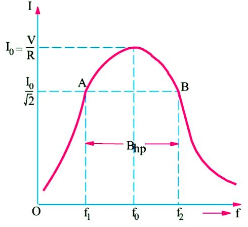
That is why the two points A and B on the resonance curve are known as half-power points and the corresponding value of the bandwidth is called half-power bandwidth Bhp. It is also called –3dB bandwidth. The following points regarding half-power point A and B are worth noting. At these points,

1. Current is Io/√2

2. Impedance is √2.R or √2.Z

3. P1 = P2 = P0/2 

4. The circuit phase angle is θ = ± 45°

5. Q = tan θ = tan 45° = 1

6. 

AdBlock-2
Resonance Curve
Figure B

It is interesting to note that Bhp is independent of the circuit capacitance.

Read article – R-L-C circuit

Visit NCERTplanet.com for NCERT solutions and Textbook downloads